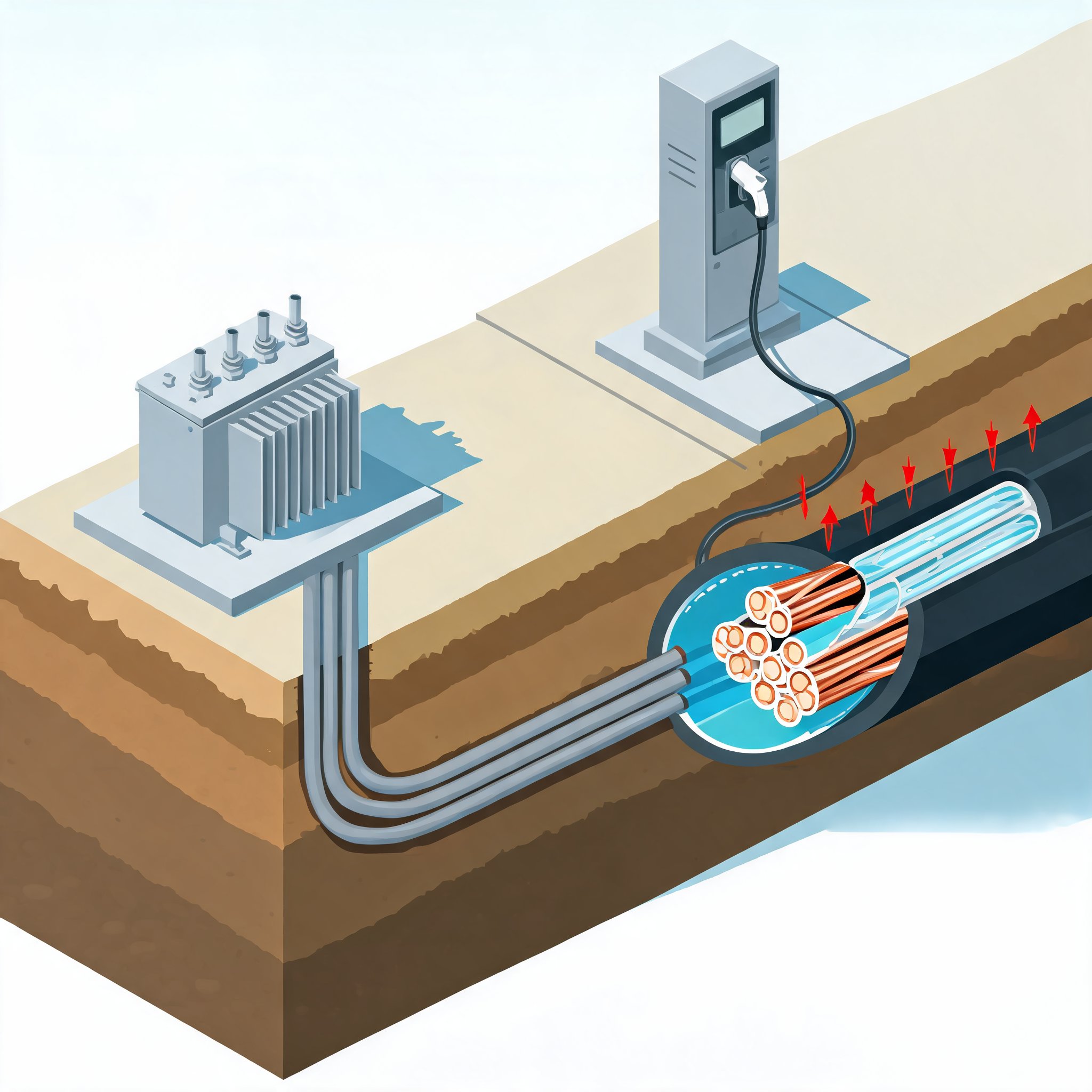
As electric-vehicle charging sites grow from a few dispensers into fleet-scale installations, the cable engineering problem now runs from the utility transformer to the vehicle connector. In an interview, Southwire's Joe Fawcett, a business development sales manager for eMobility infrastructure solutions, and Kevin Wahl, lead consulting engineer in Southwire CableTechSupport Services, described two halves of the same heat problem: medium-voltage feeders and duct banks underground, and the flexible charging cable that the public twists, drops and sometimes runs over.
Connector and cooling constraints
The move to the North American Charging Standard has not simplified the dispenser cable. Wahl said NACS uses a smaller connector and the same pins for AC and DC, which allows a lighter, smaller cable but forces more performance out of thinner conductors. The connector can still be heavy, putting strain on the cable at the vehicle end, so grommets and strain relief matter. Higher-frequency DC fast charging also creates electrical noise, making shielding for control pilot, proximity pilot and temperature-sensing wires a design issue. Wahl said braid shields add flexibility but cost and manufacturing steps, while foil shields with a drain wire can be adequate in some applications.
At higher currents, cable designers first add copper, then split large conductors into four smaller parallel wires to keep the cable smaller and more flexible. At megawatt charging levels around 1,500 A, passive cooling gives way to liquid cooling, which requires chillers at the site. Wahl said the cable design depends on whether the coolant is a water-glycol mixture or a dielectric oil, its heat capacity, the flow rate and whether cooling is direct—copper immersed in oil—or indirect, with liquid tubes surrounded by insulated copper. The return path also matters because the liquid is warmer after passing the first conductor. The cable must meet the target charge cycle and work with the dispenser's chiller.
Wahl identified cable management as a major real-world failure mode. Heavy cables held by a small ring, as at many fueling sites, can droop past their minimum bend radius, kinking copper and rippling the jacket. Repeated twisting in the same direction can produce corkscrewing. Southwire uses neutralization in cabling to reduce back-twist and cable memory. Wahl was part of a NEMA committee that produced NEMA EVSE 40007 guidelines for charging-cable management, including larger U-shaped supports or automated systems that pull the cable back in. He said cable makers can recommend such measures but cannot fully design around poor management.
Installation and thermal planning
Fawcett's side of the site addresses a different failure path. Conventional underground work glues PVC conduit in a trench, pulls a rope, then pulls conductors as separate operations. Southwire's cable-in-conduit product arrives on one reel with conductors already inside HDPE conduit, eliminating the wire-pulling step and separate reels and fittings. Fawcett said the conventional approach can damage cable when coils are rolled out on gravel, glass or broken bottles, or when wire rubs against conduit edges or switchgear during pulling. In one case, a field engineer pulled wire from conduit months after a site went live and found tire tracks on it; the cable had been run over while lying on the ground before installation. In another, debris wore through jackets until a hot conductor shorted to neutral and the dispenser failed.
Southwire calculates that cable-in-conduit saves 25% to 30% of total cost, and more on labor, according to Fawcett. He said the product carries a premium but pays back the investment by the time installation is complete—a company claim rather than an independently verified result. CIC is not universal: Fawcett said it may not fit very short runs or transitions from underground to above ground because HDPE conduit cannot be exposed and must be buried or encased in concrete. Longer, repetitive runs offer the greatest labor savings.
Higher power also changes thermal planning. Fawcett said EV sites are often built like duct banks without being treated as such: conduits or cables are stacked without spacing, so they cannot dissipate heat. Soil thermal resistivity and concrete properties matter. Wahl said concrete suppliers can differ in thermal resistivity, or rho, so calculations from one site may not transfer across town. The familiar strategy of installing aluminum now and upgrading to copper later has also weakened. Aluminum typically needs about two gauge sizes larger than copper for the same ampacity, but Wahl said expansions now often double station size rather than add one dispenser, so a simple conductor swap cannot deliver the added power. He said developers are therefore installing empty duct banks, staging pavement work and using directional boring to add capacity later without disturbing existing surfaces.
On the cable side, Wahl said most projects still rely on UL qualifications or engineering evaluations. Boost modes allow charging above a cable's rated capacity for a limited time, followed by a cooldown at or below the maximum. UL's temperature-rise test helps determine conductor size and qualify the cable assembly for the intended boost mode.
Fawcett expects fleet charging to be a major driver of cable demand in the next five years, beyond megawatt charging. A highway stop serves cars arriving at different times; a depot's delivery vehicles return around the same time and need to charge together, requiring much higher ampacity. Battery storage can absorb daytime capacity and level the site's load when vehicles return. Wahl added that such sites may also need PV wire for solar, hookup cables for batteries, and more data, control and signaling cables as operators stagger charging within grid limits. The cable designs may follow familiar principles, but the amount and complexity of cable per site are rising.